Our FOSREM (also FOM-MEM) is FORS bases on a technical implementation of the Sagnac effect (description see subpage “Background”). The construction contains of the two interdependent parts: optical and electronic. The optical part, named Optical Head, generates the phase shift proportional to the detected rotation rate which is perpendicular to the sensor loop plane, which is described by following formula:
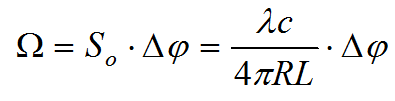 where S0 is the optical constant of the interferometer depending on the used wavelength, the velocity of the light in the vacuum c, the length of fiber in the sensor loop L and the sensor coil radius R.
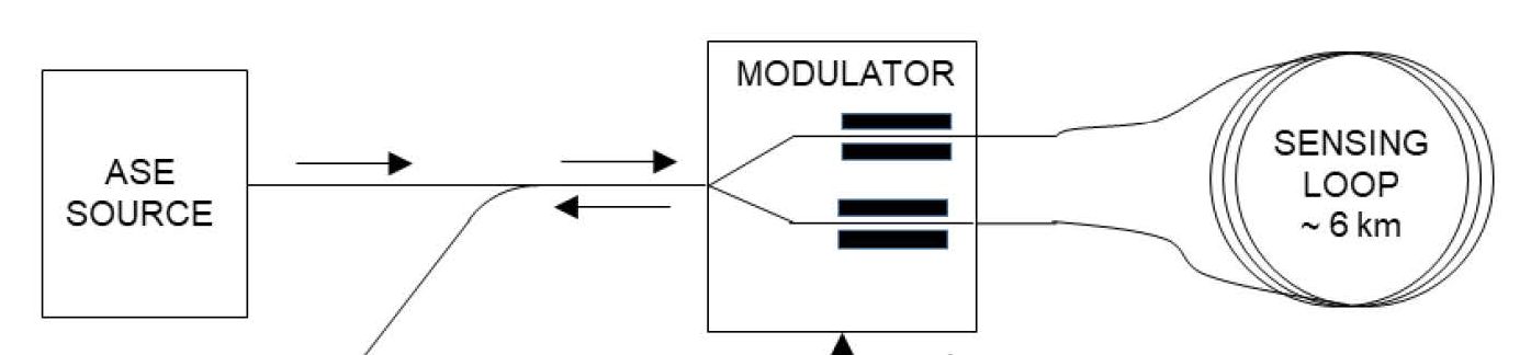
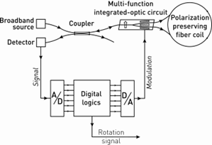
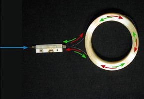
The optical part (see below) contains of the: wideband, low coherence source such as ASE, X-type fibre-optic coupler, MIOC – muti-integrated optical circuit (contains planar polarize, Y type coupler with phase modulator) and the sensor loop. This configuration guarantees that only nonreciprocal effect in the system is the Sagnac effect. The depolarized light emitted by ASE is introduced to MIOC via X-coupler and two output beams from MIOC propagate in the sensor loop in opposite direction. The interference pattern which is a result of the interference phenomenon in the Y-coupler protects measurement rotation rate iby detector located in the second input of X fibre-optic coupler.
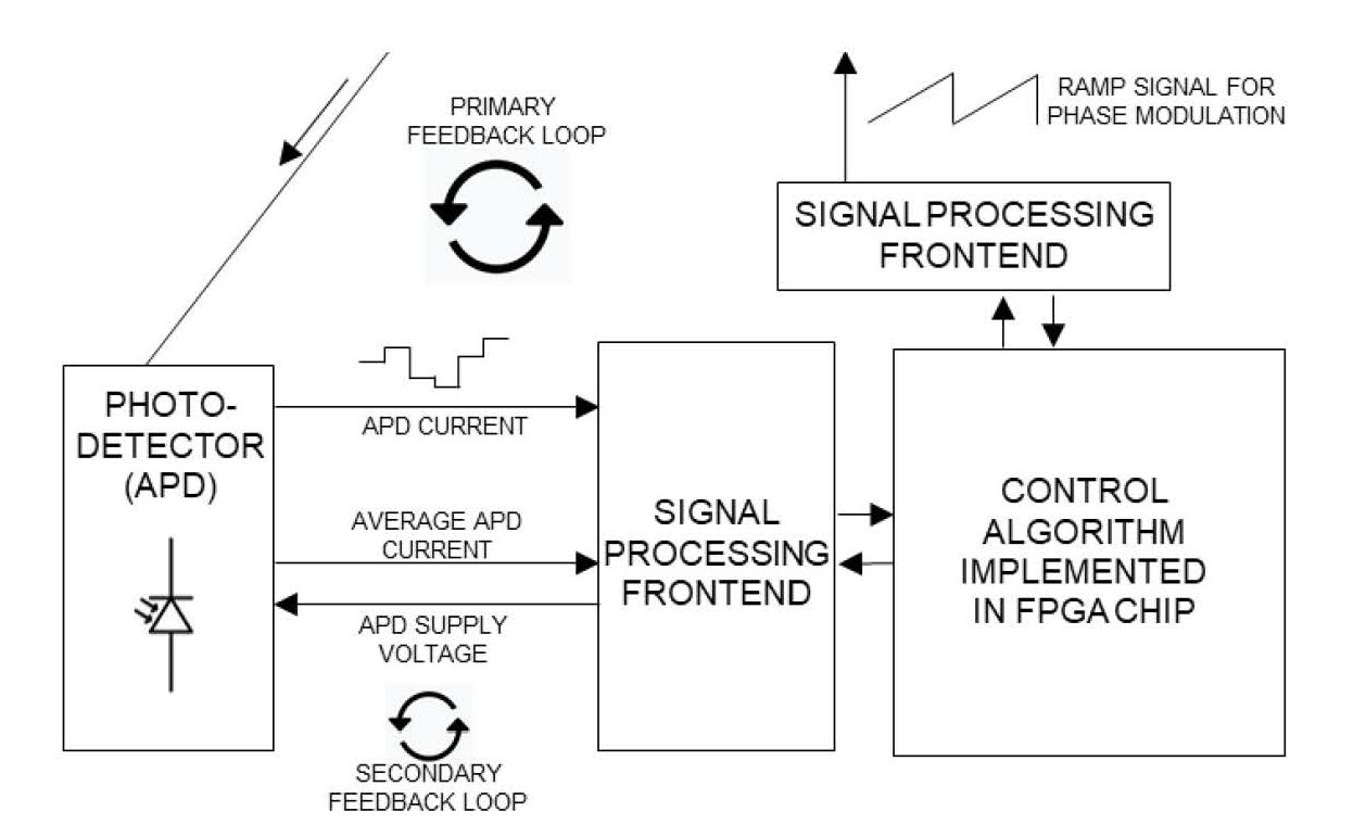
The second part of the system, the electronic part (see below), realizes the closed-loop detection in digital fporm. This part based on FPGA and applies the system called Power Communication Unit (PCU) protects power supply and data store at SDD which additional is equipped with the built-in web server. PCU allows to remote control the system’s operation by a special FOSREM Telemetry Server. Control is performed in real time through a VPN FOSREM network. FOSREM Telemetry Server stores data from particular devices which have been made in FOSREM technology.
The main advantages of FOS6 (see below together with PCU) developed under FOSREM project is:
- high sensitivity and wide range of application fields;
- wide detection frequency band pass (0.01 -100 Hz);
- angular random walk (ARW) ~50 nrad/Sqrt(s),
- bias instability (BI) < 20 nrad/s
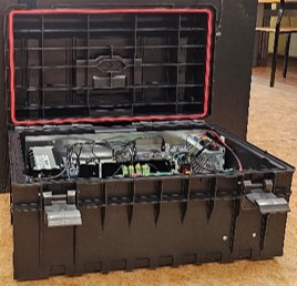
- mobile construction, dimensions: 340 x 330 x 315 mm, weight: less than 18 kg;
- Power consumption: less than 15 W;
- Connectivity: Ethernet 100 Mbps with PoE, (fiber option);
- Precise 20 bits conversion;
- Powerful ARM two-core microprocessor with high speed FPGA;
- Internal Access Point for device configuration;
- Web-Based Management Interface;
- Internal 512 GB SSD for data storing;
- Up to 24 hours autonomous operation without external power;
- Up to 30 days autonomous operation in local data storage mode.
Network Implementation
The Network, performed for FORS – (Fibre-Optic Rotational Seismometer) which have been constructed according to FOSREM technology (for instance FOS6), uses VPN connection to integrate all sensors in one system. Each sensor contains of a built-in web server which is connected to the FOSREM Telemetry Server by VPN. This server stores data from particular devices and allows changing all operations parameter for chosen sensor. The remote control is performed in real time through a VPN FOSREM network. Each user has access to his sensor in order to store information on his own computer.
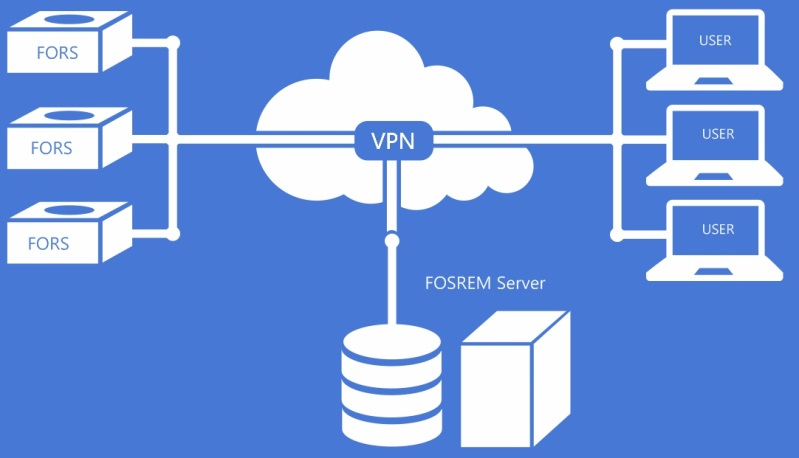
Advantages of FOSREM network implementation:
- Remote control for each FORS users by VPN
- The constant monitoring of the devices operation and gathering the recorded data
- Easy firmware upgrade by VPN
- Personal configuration and access for any FORS according to customer requirements
FOM-MEM as prectical example of Network Implementation
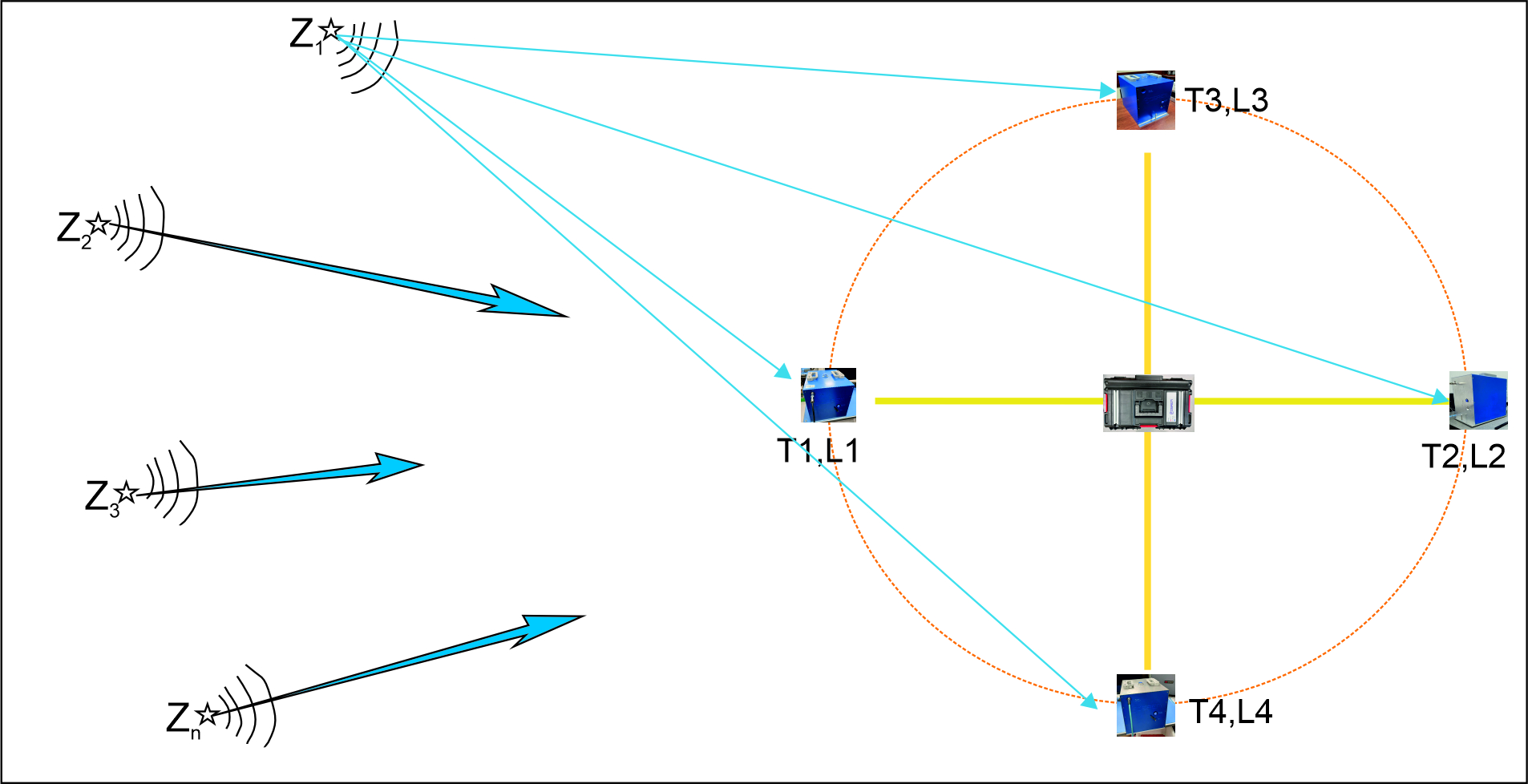
Based on above network implementation FOM-MEM is developing as system where four FOS6 are conected in one network node (four FOS6 connected in star configuration via 80 m long cable with one PCU working as Data Analyze Unit). The high correlation of data recorded by each FOS6, together with high temporal data synchronization (about 100 ns) will allow in the future:
- determining the location of the source of the disturbance (by analyzing the time of registration of the disturbance by individual FOS6 at a given or several nodes) – patent pending P.450531 Republic of Poland Patent Office,
- idetification of source type – natural, artificial, etc.(by analising their frequency spectrum with application AI) – patent pending P.450532 Republic of Poland Patent Office.
FOG – fibre-optic interferometer the best solution
FOG uses the Saganc effect to determine the angular changes of an object in space (for aircraft, these are angles around 3-orthogonal axes referred to as the Roll, Yaw and Pitch axes – see background). In practice, this means that the angular velocity value, determined based on the Sagnac effect in a given direction, must be integrated:
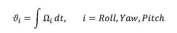
where Wi – the angular velocity in the i-axis, defined based on the Sagnac effect, and dt the integration time ensuring the required sensitivity.
The practical use of the device as a FOG for a given INS grade (see background) imposes restrictive requirements on its design concept referred to as the classical configuration of a fibre gyro [H.C. LeFevre, The Fiber-Optic Gyroscope, 2nd Ed. Artech House, 2014], having:
- minimal or reciprocal configuration providing single-mode operation,
- polarization-preserving fiber coil (typically 100 m to 10 km long) with appropriate winding to eliminate temperature drift
- multi-function integrated-optic circuit (MIOC) with proton-exchanged single-polarization waveguide on LiNbO3, providing very high polarization-rejection and Y-junction and pair of push-pull, low-voltage, wide-frequency phase modulators enabling the implementation of close-loop operation,
- broad-spectrum source (unpolarized erbium ASE source) for the reduction of nonreciprocal phenomena other than the Sagnac effect for best performance,
- all-digital signal processing electronics to ensure high linearity over the entire measuring range.